
-
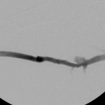
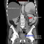
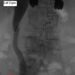
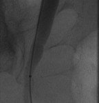
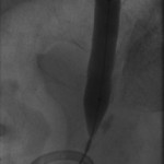
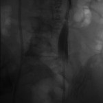
- Surveillance left arm brachiobrachial fistulagram before intervention. Observe the critical stenosis of the mid brachial vein and the saccular aneurysms proximal to it.
-
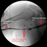
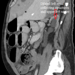
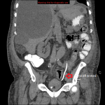
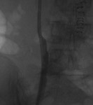
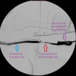
- Surveillance left arm brachiobrachial fistulagram before intervention. Observe the critical juxta-anastomotic stenosis of the brachial vein and the saccular aneurysms distal to the stenosis. The purple arrow identifies the left brachial artery, the red arrow points at 2 juxtaposed aneurysms of the left brachial vein, while the red arrow identifies the juxta-anastomotic stenosis of the vein.
-
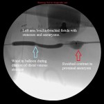
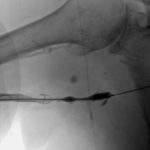
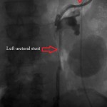
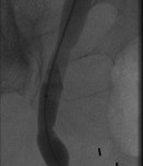
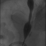
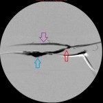
- Image of balloon angioplasty of the stenosis of the mid left brachial vein. There is residual contrast in the aneurysm.
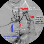
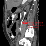
These 3 images are diagnostic angiograms of a left arm arteriovenous fistula (AVF) between the brachial artery and the brachial vein. The end of the proximal left brachial vein (the part of the vein closer to the elbow) was anastomosed to the side of the distal left brachial artery at the creation of the fistula and the stump of the vein ligated.
The study is more appropriately named a fistulagram and shows that the left brachial artery and the arteriovenous anastomosis are normal, with an abnormal venous limb of the circuit: the venous limb has a short juxta-anastomotic stenosis separated from 2 juxtaposed saccular aneurysms by a short segment of normal vein; distal to to the aneurysms is a smooth tapering stenosis that merges into a normal segment of the vein. The rest of the brachial vein, the axillary vein, and the central veins are normal, but the images are not included in the gallery. Notice that a complete picture of the arterial and venous limbs of the circuit was obtained by injecting radiocontrast through the sheath between the aneurysms and the juxta-anastomotic stenosis, suggesting high intravenous pressure proximal to the stenosis in the mid brachial vein.
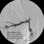
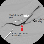
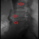
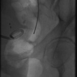
To fix the problems, I punctured the vein proximal to the aneurysms and secured the access with a sheath. I passed a balloon over a guidewire to the distal stenosis and dilated it with optimal outcome. I secured a second access through the normal segment of the vein distal to the stenosis (pointing towards the patient’s elbow) and through it advanced the balloon to the juxta-anastomotic stenosis. I dilated it with optimal outcome. I did not address the aneurysm at the same session, but placed it under periodic clinical and imaging observation. The final fistulagram showed rapid blood flow through the venous outflow limb with satisfactory calibers at the treated segments.
The natural history of situations such as this is that the flow of blood through the fistula gradually slows down as the stenoses worsen, coming to a full stop when the obstructions complete. Clot forms and the access fails. Warning clinical signs of impending failure include prolonged dialysis times, diminished venous flow rates, high static venous pressures, prolonged bleeding at needle entry site upon removing the dialysis needle, a string of clot adherent to the needle at withdrawal, water-hammer pulse over the segment of the vein proximal to the stenosis that diminishes as the stenosis worsens, a thrill of variable strength, and a harsh murmur amongst others. It is at this time that patients should be referred for diagnostic fistulagram, not when the access fails. It costs more in money, effort, time, and patient morbidity to salvage thrombosed dialysis accesses than intervening on malfunctioning but patent ones. The outcomes are also poorer .
Arterial limbs of dialysis accesses are not as problematic as their venous limbs, which are often plagued by stenoses and aneurysms. The latter are caused by iatrogenic venous injury during surgical creation of the access and repeated punctures at dialysis and during diagnostic and surveillance imaging. They occur less frequently or develop slowly when such punctures are rotated over the skin overlying the vessel.
Stenoses are easily treated with balloon dilation, while aneurysms may be observed over time for growth. They should be repaired surgically or be endovascularly isolated from the circulation with covered stents, when the threat of their rupture rises or they become reason for repeated failing of an access.